Hardware setup:
Before switching on any light source, ensure that the SiPM bias is well below the breakdown voltage (~38 V) or preferably 0 V, or at least that a proper light cover is used for the tileboard.Connect the tileboard to the tileboard tester (TBT) through the QTH/QSH port via the adapter and power on the TBT (~10 V)
With adapter (from DESY):- Place the tileboard with the screw mounts such that the surface with SiPMs, LEDs and tiles is facing downwards, and the face with the HGCROC, GBTSCA etc mounted points upwards
- Rigol dual power supply (digital, controlled with RPi - see below) and an analog tileboard power supply are used
- Connect the yellow cable of the adapter to the SiPM bias, the green cable to the LED bias and the red cable to the tileboard supply - they are all banana jacks of very short length (cables are all labeled)
- Connect the black cable (board GND) to the negative terminals of one of the power supplies, short all the three negative terminals to their respective GNDs and short the 3 GNDs together
- Tileboard bias should be ~10 V (ideally 10.5 V or 11 V and not exceeding 12 V (verify this max))
- Place the tileboard such that the surface with SiPMs, LEDs and tiles is facing upwards, and the face with the HGCROC, GBTSCA etc mounted points downwards
- The external tileboard bias will not be used since the power to the tileboard is directly provided by the TBT through the ribbon cable
- The external LED bias will not be used either, since the value can be entered with a DAC in the script https://github.com/snabili/HGCal_QCTests/blob/main/sipm_mezz_v2.py using python ./sipm_mezz_v2.py --setLED="digital_value" --status, and the status argument outputs the voltage and current for the LED and SiPMs
Voltage control with USB from Raspberry Pi:
DP 800 series Rigol dual power supply is being used, with Ch 1 ranging from 0 to 60 V and used for SiPM bias and Ch 2 ranging from 0 to 8 V and used for LED biassource py_env/bin/activate (For running the python environment already installed) python3 RigolControl _new.py -sb "SiPM_bias_voltage" -lb "LED_bias_voltage" -rs 1 If any voltage has to be set to 0, use the value 0.001 (precision is 1 decimal place greater than supply readout)
Software setup:
For software and firmware installation instructions refer to https://readthedocs.web.cern.ch/pages/viewpage.action?pageId=306970874 Internal IP Address and username of TBT (previously assigned) - HGCAL_dev@10.42.0.63Internal IP Address of Gantry desktop - 10.42.0.200
The firmware has to be loaded every time the TBT is powered on - run https://github.com/snabili/HGCal_QCTests/blob/main/setup/firmware_load.sh Expected output format:Previously loaded firmware: /opt/cms-hgcal-firmware/hgc-test-systems/tileboard-tester-v2p0
Using bitstream: /opt/cms-hgcal-firmware/hgc-test-systems/tileboard-tester-v2p0/tileboard-tester-v2p0.bit
Using device tree overlay: /opt/cms-hgcal-firmware/hgc-test-systems/tileboard-tester-v2p0/device-tree/pl.dtbo
Loading the bitstream took: 0.465s
Loaded the device tree overlay successfully using the zynqMP FPGA manager
Two terminal windows to be opened by logging (ssh) into the TBT [for daq-server i.e. the fast controls server and i2c-server i.e. the slow control server] and two windows on the remote machine, which is the gantry desktop [for the daq-client and the actual script to be run]
daq-server → https://github.com/snabili/HGCal_QCTests/blob/main/setup/daq-server.sh i2c-server → https://github.com/snabili/HGCal_QCTests/blob/main/setup/i2c-server.sh *Expected output:*14-07-23 06:36:32.011328 [547804184576] WARNING - Address overlaps observed - report file written at "/tmp/HGCAL_dev/uhal/OverlapReport-opt-cms-hgcal-firmware-hgc-test-systems-active-uHAL_xml-modules-link_capture_daq_global.xml.txt"
14-07-23 06:36:32.015675 [547804184576] WARNING - Address overlaps observed - report file written at "/tmp/HGCAL_dev/uhal/OverlapReport-opt-cms-hgcal-firmware-hgc-test-systems-active-uHAL_xml-modules-link_capture_daq.xml.txt"
14-07-23 06:36:32.020636 [547804184576] WARNING - Address overlaps observed - report file written at "/tmp/HGCAL_dev/uhal/OverlapReport-opt-cms-hgcal-firmware-hgc-test-systems-active-uHAL_xml-modules-link_capture_trg_global.xml.txt"
14-07-23 06:36:32.024703 [547804184576] WARNING - Address overlaps observed - report file written at "/tmp/HGCAL_dev/uhal/OverlapReport-opt-cms-hgcal-firmware-hgc-test-systems-active-uHAL_xml-modules-link_capture_trg.xml.txt"
14-07-23 06:36:32.028819 [547804184576] WARNING - Address overlaps observed - report file written at "/tmp/HGCAL_dev/uhal/OverlapReport-opt-cms-hgcal-firmware-hgc-test-systems-active-uHAL_xml-modules-link_capture_selftrig_global.xml.txt"
14-07-23 06:36:32.030595 [547804184576] WARNING - Address overlaps observed - report file written at "/tmp/HGCAL_dev/uhal/ OverlapReport -opt-cms-hgcal-firmware-hgc-test-systems-active-uHAL_xml-modules-link_capture_selftrig.xml.txt"
14-07-23 06:36:32.040022 [547804184576] WARNING - Address overlaps observed - report file written at "/tmp/HGCAL_dev/uhal/OverlapReport-opt-cms-hgcal-firmware-hgc-test-systems-active-uHAL_xml-modules-trigger-xbar-trigger-xbar-0.xml.txt"
14-07-23 06:36:32.043532 [547804184576] WARNING - Address overlaps observed - report file written at "/tmp/HGCAL_dev/uhal/OverlapReport-opt-cms-hgcal-firmware-hgc-test-systems-active-uHAL_xml-fw_block_addresses.xml.txt"
[I2C] Found 8 address(es) on bus 0 - This is mandatory to ensure that the server is running smoothly
[I2C] Found 0 address(es) on bus 1
[I2C] Found 0 address(es) on bus 2
[I2C] Found 0 address(es) on bus 3
[I2C] Found 0 address(es) on bus 4
[I2C] Found 0 address(es) on bus 5
[I2C] Found 0 address(es) on bus 6
[I2C] Found 0 address(es) on bus 7
[I2C] Found 0 address(es) on bus 8
[I2C] Found 0 address(es) on bus 9
[I2C] Found 0 address(es) on bus 10
[I2C] Found 0 address(es) on bus 11
[I2C] Found 0 address(es) on bus 12
[I2C] Found 0 address(es) on bus 13
[I2C] Found 0 address(es) on bus 14
[I2C] Identified Single-Chip (Char) board- This is mandatory to ensure that the server is running smoothly
[roc_s0] GPIO reset
Scripts are in the $hostarea/hexactrl-sw/hexactrl-script
After all this is successful, run the slow control script https://github.com/snabili/HGCal_QCTests/blob/main/TB3_SlowControl_mat.py to verify that all the bias voltages (mainly SiPM and LED bias) are applied correctly and supply voltages are within rangePLL_LCK=1
VCC_GBTSCA ~ 1.5 V
VPA (HGCROC supply voltage) ~2.5 V
* Other diagnostic parameters -
- Run the slow control script and measure CLK and data signals (SCL and SDA) at R182 and R181
Inserting waveform screenshots here - Run https://github.com/snabili/HGCal_QCTests/blob/main/pedestal_run.py (pedestal acquisition for all channels) and check whether trigger pulse is appearing at R591This will produce several (10000 is the current setting) events for each channel and plot the average and stddev (noise) for each channel
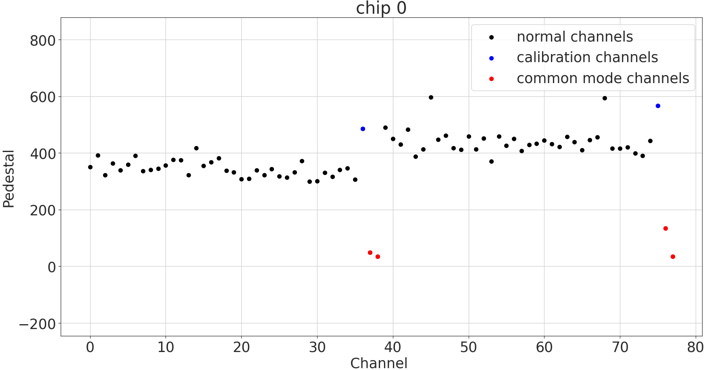 Example of a plot with average values of pedestals per channel for https://github.com/snabili/HGCal_QCTests/blob/main/configs/roc_config_ConvGain12.yaml
Current issues:
Very large noise levels obtained for the second half of the board (half 1) due to bimodal pedestals which in turn arise due to corruption in a significant proportion of the events (from 10% upto 70% for some runs)
This has been resolved to some extent by not including the RPi in the tileboard tester ssh path
Pedestal alignment:
This is done in 4 steps, one script and one parameter at a time- Channelwise inverting shaper voltage (ref_dac_inv)
- Global inverting shaper voltage (10 bit Inv_vref)
- Global non inverting shaper voltage (10 bit Noinv_vref)
- Channelwise leakage current at conveyor stage (6 bit DACb) - This is the main parameter responsible for the flattening
At the moment steps 2 and 4 are working, step 1 is producing a key error in ref_dac_inv, and the fit in step 3 is failing
This gives a pedestal value close to 0, and this gives problems with producing a single photon spectrum (sps) via external injection [Not actually the purpose of pedestal alignment]
New version (ROC v3)
Apparently ref_dac_inv is now trim_inv, which is tuned using a pedestal scan script
DACb step is yet to be added- Pedestal scan (setting targets individually for either half of the board)
- Tuning in global inverting shaper voltage (10 bit Inv_vref)
- Pedestal scan again (to refine the results)
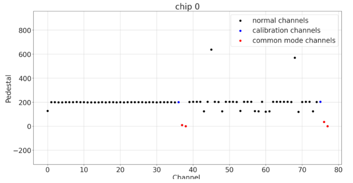
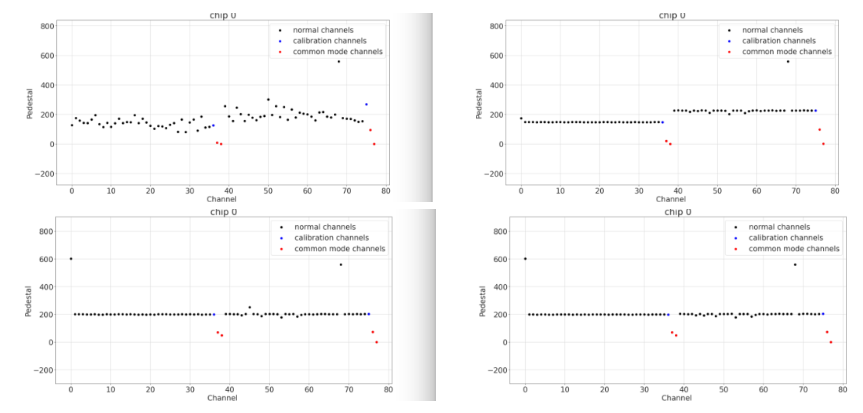 The current alignment process (steps 0 through 3)
 Example of bad alignment due to bit overflow
SPS (Single Photon Spectrum) with Phase scan via external injection
This uses an optical trigger, which could be the LEDs Run https://github.com/snabili/HGCal_QCTests/blob/main/LED_scan_testbeam_new.pyPhase scan is only done to find the phase (slice in time) where the integrated pulse amplitude is maximum for best sps results - each phase is associated with its own separate .root file
Example of an sps for BX 24, phase 9 from the start of the trigger with ~42 V internal SiPM bias and 5.8 V LED bias and using https://github.com/snabili/HGCal_QCTests/blob/main/roc_config_ConvGain12.yaml - typically conveyor gain should be large enough to obtain well separated peaks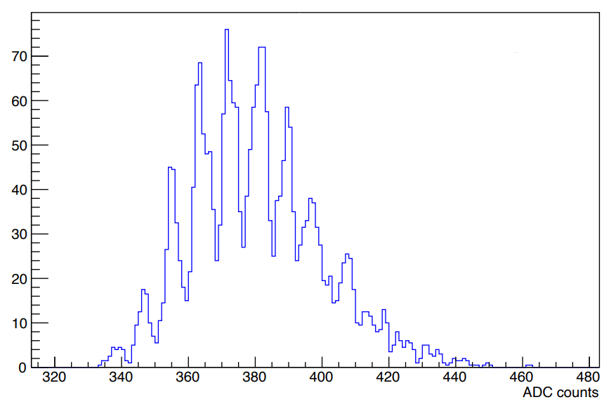
Ideas, requests, problems regarding Foswiki? Send feedback